


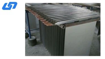
Titanium copper composite bar
Two process methods to produce the titanium copper composite bar:
1. Hot extrusion + cold drawing
2. Explosive cladding + hot rolling
Product Introduction
1. Purpose
This document specifies the ultrasonic testing method used to verify the bonding quality of titanium–copper clad bars.
The inspection is performed to ensure the integrity of the cladding layer and to identify any non-bonded areas between titanium and copper.
2. Testing Equipment
2.1 Ultrasonic Flaw Detector
An A-scan pulse-echo ultrasonic flaw detector shall be used for inspection.
The instrument performance shall comply with JB/T 10061 or equivalent standards.
2.2 Probe
The inspection shall be carried out using a straight-beam ultrasonic probe with the following specifications:
Frequency: 2.5 MHz – 5 MHz
Crystal diameter: 10 mm – 20 mm
2.3 Couplant
A suitable couplant shall be used to ensure effective transmission of ultrasonic waves.
Acceptable coupling media include:
Clean water
Industrial inspection oil
2.4 Reference Test Bar
A standard reference bar shall be used for sensitivity calibration. The reference bar shall meet the following requirements:
Same material composition as the inspected bar
Same dimensions
Similar acoustic characteristics
Fully bonded titanium–copper composite structure
3. Inspection Procedure
3.1 Inspection Method
The multiple back-wall echo reflection method shall be used for inspection.
Testing may be conducted using either:
Contact ultrasonic inspection
Immersion ultrasonic inspection
3.2 Inspection Surface
For bars with rectangular, square, or drum-shaped cross-sections, inspection may be performed on any axial surface to ensure full coverage of the cladding interface.
3.3 Sensitivity Calibration
The ultrasonic testing system shall be calibrated so that the fifth back-wall echo of the reference test bar reaches 50% of the full screen height on the ultrasonic display.
This calibration level shall be used as the inspection sensitivity setting.
3.4 Scanning Speed
During inspection, the probe scanning speed shall not exceed 150 mm/s to ensure accurate detection.
4. Evaluation Criteria
4.1 Bonded Area Identification
If the back-wall echo is clearly visible and no interface echo appears, the inspected area shall be considered fully bonded.
4.2 Non-Bonded Area Identification
If the back-wall echo decreases significantly or disappears, and an interface echo is detected, the inspected area shall be classified as a non-bonded area.
4.3 Determination of Non-Bonded Boundary
When scanning along the axial direction, the boundary of the non-bonded area is determined when the interface echo disappears at the center of the probe.
5. Acceptance Criteria
A titanium–copper clad bar shall be considered acceptable if the detected non-bonded areas meet the requirements in Table 1.
Table 1 – Cladding Quality Acceptance Criteria
Inspection Area | Requirement |
Within 100 mm from each end | Maximum single non-bonded axial length < 10 mm; cumulative length on one inspection plane < 20 mm |
Other areas | Maximum single non-bonded axial length < 50 mm; cumulative length per meter on one inspection plane < 100 mm |
6. Remarks
Surface roughness of the inspection surface or fluctuations in the back-wall echo caused by the copper core structure shall not affect the final evaluation of the cladding quality.
Hot Tags:
You Might Also Like


Send Inquiry